
Three Phase Inverter / induction motor driver
- Category: Hardware, Software
- My Participation: 100%, 100%
- Progress level: 100%
- Project date: 2015
Details
Project was development for Master's dissertation.
-
Voltage input: 1ph / 230 V
Current input: 2-3 A RMS
Output current: 3 A RMS per phase
Output Voltage: 220V RMS line voltage
Output frequency: 0 – 100 Hz
PWM frequency: 5 – 15 kHz
Hardware:
-
CPU: STM32F446
Communication: USB, CAN.
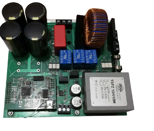
Power stage: LC input filter, 6x IGBT transistors, transistor RC snubbers, separately gate-driver power supplies etc.
Galvanically isolated power stage
Sensors: current sensor per phase, rotational speed sensor, thermistor (transistors temp. monitoring)
Firmware features:
-
Control algorithm: scalar V/f = const. with parameterized characteristics. Possibility to extend for Field
Oriented Control of induction motors
PWM signal for transistors gate driving are generated using DMA and dedicated Timer output channels.
Sinus table is dynamically scaled (for different output voltage RMS values)
Data acquisition from all sensors, real-time data streaming including phase currents (3kHz sampling)
Over-current protection.
Parameters of device are controlled by protocol - commands (USB communication)